inside EEEInst 002 WIRE AND CABLE
iNSIDE EEE INST-002
Imagine you are strapped into the payload fairing of a heavy lift rocket launching from Cape Canaveral. The countdown hits zero. The vibration is violent. You are pushed back into your seat at three times the force of gravity.
In just eight and a half minutes, the main engines cut off. The shaking stops instantly. You are perfectly weightless.
You have just arrived in Low Earth Orbit, commonly known as LEO.
But space is not a uniform vacuum. If space is an ocean, the zones surrounding Earth are broken into distinct environments, each presenting its own brutal set of physics. For aerospace engineers, understanding these zones is the difference between mission success and catastrophic electrical failure.
The Shallow Reef: The LEO Environment
LEO is the chaotic, shallow reef right off the beach. You are only about 300 miles above the surface of the Earth. To put that in perspective, if you drove your car straight up at highway speeds, you would be there in about five hours. In a rocket, it takes less than ten minutes. The technical boundary of LEO ranges from about 100 miles up to 1200 miles.
The environment here is beautiful but brutal. Because you are so close to the Earth, the planet pulls on you with immense gravity. To keep from falling back into the atmosphere, your spacecraft has to travel at a blistering 17500 miles per hour.
At that speed, you completely circle the globe every 90 minutes. If you look out the window, you see a blinding sunrise or a pitch-black sunset every 45 minutes. The thermal shock is terrifying. The outside of your spacecraft swings from 250 degrees Fahrenheit in the sun to negative 250 degrees in the dark, over and over again.
Furthermore, LEO is not entirely empty space. There are trace amounts of atomic oxygen floating around. It is a highly reactive gas that literally eats away at exposed plastics and wire insulation through chemical sputtering. Aromatic polyamide insulation (like Kapton) is rapidly degraded by exposure to atomic oxygen. This is also the most crowded highway in the solar system, shared by the International Space Station, thousands of commercial small satellite constellations, and millions of pieces of debris moving like bullets.
The Next Level: Medium Earth Orbit (MEO)
If your spacecraft fires its engines again, you push out of the shallow reef and into the deep ocean. You coast upward for about three hours. The Earth begins to shrink in your window, turning from a massive, fast-moving blur into a distinct blue marble.
You have arrived in MEO, specifically parking at about 12500 miles above the Earth.
The environment has completely changed. Because you are further away from the gravitational pull of Earth, you do not have to fly as fast to stay in orbit. Your speed drops to about 8700 miles per hour. Instead of circling the Earth every 90 minutes, a single orbit now takes exactly 12 hours. This is the Navigation Zone, where the Global Positioning System satellites live. Everyone can thank LMCO for GPS.
However, MEO holds a deadly invisible threat. At this altitude, you are flying directly through the heart of the Van Allen radiation belts. These are massive magnetic fields trapping highly energetic solar wind and cosmic radiation. It is a highly radioactive gauntlet. If a spacecraft is not heavily shielded and wired with radiation hardened materials, the background radiation in MEO will fry its computer brain in a matter of days and cause standard plastics to become brittle and shatter.
The Final Frontier: Geostationary Earth Orbit (GEO)
One final thruster burn enters a highly elliptical transfer orbit. After a long coast taking another five hours, you reach the absolute pinnacle of Earth orbit. You are exactly 22236 miles above the equator.
At this extreme distance, the environment is dead quiet and incredibly cold. You are entirely clear of the Earth atmosphere and the worst of the radiation belts.
The most magical thing about GEO is the physics of your speed. At 22236 miles up, your required orbital speed drops to about 7000 miles per hour. Coincidentally, this means it takes you exactly 24 hours to complete one single orbit. Because the Earth also takes 24 hours to rotate, you are completely synchronized with the planet.
If you look out the window at North America, that landmass stays perfectly framed in your window all day, every day. You never move relative to the ground below. This is why a satellite dish on a house never has to move; it is pointed at a GEO satellite permanently parked in the exact same patch of sky.
Note: Actual transfer times and precise orbital parameters vary by launch trajectory, inclination, and propulsion profile.
Decoding NASA EEE INST 002: Wire and Cable
While the entire NASA EEE INST 002 document breaks aerospace components down into many different commodities, today we are strictly talking about the wire and cable section. Section W1, which governs Wire and Cable, spans pages 304 through 337 of the official EEE INST 002 addendum.
Over the years, EEE INST 002 has become an absolute industry favorite. It is incredibly fair, yet it establishes rigid guard rails that are highly specific when navigating between Level 1 and Level 3 requirements. Ultimately, this specification helped modernize part selection across the board, serving as the ultimate blueprint for product parts identification. It empowers leading engineers as they embark on new journeys in product development for the next generation of spaceflight.
This document breaks aerospace components down into three specific screening levels based on the mission lifespan and risk tolerance:
- Level 1: Highest reliability and lowest risk. Used for human boarded vessels or missions lasting 5 years or greater. This requires the absolute highest manufacturing control.
- Level 2: Low to moderate risk. Used for missions lasting 1 to 5 years.
- Level 3: High risk or unknown risk. Intended for short missions lasting less than 2 years where cost constraints demand commercial or lightly screened parts.
The Four Major Hazards
According to EEE INST 002, wire and cable selection must account for four major hazards specific to the vacuum of space:
- Outgassing: In a vacuum, unreacted additives and moisture evaporate from wire insulation and condense on cold surfaces, blinding optical lenses and ruining solar panels. Section W1 dictates that all non metallic materials must pass the ASTM E595 outgassing test, requiring a Total Mass Loss of less than 1.0 percent and Collected Volatile Condensable Material of less than 0.1 percent.
- Atomic Oxygen: In Low Earth Orbit, atomic oxygen acts as a highly corrosive agent. It rapidly degrades aromatic polyamide insulation and oxidizes unprotected silver plating.
- The Red Plague: Silver coated copper wire is highly susceptible to cuprous oxide corrosion, known as the red plague, if moisture penetrates pinholes in the silver plating. EEE INST 002 strictly forbids water quenching during the wire manufacturing process to prevent this catastrophic failure. Water quenching is the rapid cooling of heated, freshly extruded wire by plunging it directly into a water bath.
- Solvent Degradation: Aggressive cleaning solvents can break down insulation mechanical strength. Solvents cause fluorinated polymers to release trace amounts of fluorine, which aggressively corrodes surrounding metals.
EEE-INST-002 Screening Level Master Matrix
Industry Spotlight: Sourcing High Reliability Components
A major shoutout goes to the team at SEA Wire and Cable for their continued support in this marketplace. By consistently stocking these mission critical, high reliability mil spec components, they bridge the gap between complex engineering requirements and real world procurement execution.
Note: Swipe horizontally to navigate all column data when viewing this matrix on mobile web browsers.
Wire and Cable Spec Breakdowns
SAE AS81044 (M81044, Mil-W-81044) Technical Overview
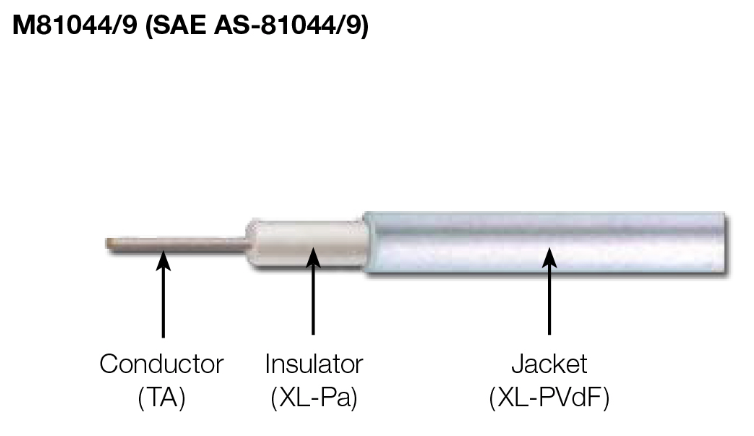
The M81044 wire series is widely used across complex military hardware and high end aerospace markets. It represents an ideal wiring selection for high density wire harnesses that must be housed within tight structural spaces. Because of its intense structural durability, it is routinely specified for use inside ground support equipment, shipboard systems, defense missiles, high performance avionics, structural airframes, and various other demanding electronic architectures.
Mechanically, M81044 wire is engineered as a dual insulated product composed of crosslinked polyalkene paired with a protective outer coating of polyvinylidene fluoride (PVF2). This rugged outer insulation boundary delivers superior physical resistance to mechanical cut through, heavy surface abrasion, aggressive common chemicals, structural cold flow, and it exhibits low smoke properties during critical failures.
All primary slant sheets within this family operate reliably across a broad temperature range from negative 65C to 150C and carry a maximum operational voltage rating of 600 volts. Procurement planners can source this configuration with tin, silver, or high strength copper alloy (HSCA) coated conductor packages across light and medium insulation thicknesses. Based on individual slant sheet configurations and core conductor thickness, the M81044 family spans seamlessly from large 4/0 leads down to fine 30 gauge options.
This product is easily stripped to allow for rapid, clean termination and multiple color configurations. Designers can utilize specialized reference systems to map out available slant sheets and precise product details. A definitive part numbering scheme dictates exactly how the part construction tracks individual slant sheet variables, target wire gauge sizes, and outer jacket colors:
- SAE AS81044 (M81044/6)
- SAE AS81044 (M81044/9)
- SAE AS81044 (M81044/10)
- SAE AS81044 (M81044/12)
- SAE AS81044 (M81044/13)
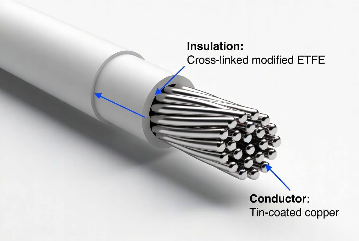
SAE AS22759 (MIL-W-22759) Fluoropolymer Wire SAE AS22759 is the dominant specification family for high-performance fluoropolymer-insulated wire used in aerospace and space applications. It covers single-conductor wires with materials such as PTFE, ETFE, and crosslinked ETFE, designed to meet the extreme demands of thermal vacuum stability, radiation resistance, and low outgassing required for spaceflight.
Official Resources and Document Downloads
Because NASA TP 2003 212242 (EEE INST 002) is a work of the United States Government prepared by federal employees, it is in the public domain. This means it is freely available for engineering teams, manufacturers, and procurement specialists to download, reference, and distribute without copyright restriction.
For your convenience, we have hosted the complete, unedited specification document directly on our servers for immediate reference.
Decoding NASA EEE INST 002: Wire and Cable
While the entire NASA EEE INST 002 document breaks aerospace components down into many different commodities, Wire and Cable, spans pages 304 through 337 of the official EEE INST 002 addendum.
Download the Complete EEE INST 002 Document Here
https://nepp.nasa.gov/docuploads/FFB52B88-36AE-4378-A05B2C084B5EE2CC/EEE-INST-002_add1.pdf
As always, due to the dynamic nature of government specifications, users are advised to check the official NASA NEPP website prior to usage to ensure they are working with the absolute latest revisions and addendums for critical flight hardware.
EEE-INST-002 Wire & Heat Shrink Selection Matrix
| NASA Screen Level | Component Commodity Type | Approved Spec Baseline | Why it is Acceptable (NASA Selection Criteria) | Testing Rigor & Hours Baseline (Level 1 vs Level 3 Justification) | Qualified Parts Stocking Source Links |
|---|---|---|---|---|---|
| Level 1 Human-rated flight or 5–15+ year lifespans |
Wire & Cable (Section W1, P. 304) |
SAE AS22759/11 SAE AS22759/12 |
Pure extruded PTFE insulation delivers absolute thermal vacuum stability, zero outgassing, and does not crack under cryogenic loads. | Ultimate Controls: Requires 100% processing lot verification. Lot qualification demands Life Testing at 100 to 500 hours at maximum rated temperatures to verify polymer stability and insulation durability against vacuum breakdown. | SEA Wire: M22759 Catalog Harbour: Extruded PTFE M22759 |
| Heat Shrink (Section T2, P. 284) |
SAE AS23053/12 SAE AS23053/18 |
High-purity PTFE and fluoropolymer profiles maintain zero volatile mass accumulation, preserving structural wall barriers under deep vacuum pressure. | Strict Conditioning: Long-term thermal aging stability tests require up to 168 hours of continuous heat exposure, tracking shrinkage ratios, tensile strength retention, and visual stress cracking to eliminate infant mortality. | Zeus: PTFE Heat Shrink Tubing Sumitomo: Sumitube KH 230 TW | |
| Level 2 Low to moderate risk, 1–5 year lifespans |
Wire & Cable (Section W1, P. 304) |
SAE AS81044 (MIL-W-81044/12) |
Crosslinked polyalkene cores with a PVDF top coat eliminate high-density wiring cold flow while resisting space radiation fields up to 100,000,000 RADS. | Reduced Overhead: Lot sample qualification relies on standard military testing loops. Life testing constraints are shortened or accepted via manufacturer QPL data rather than direct flight lot testing. | SEA Wire: SAE AS81044 Catalog TE Connectivity: SPEC 44 and SPEC 55 |
| Heat Shrink (Section T2, P. 284) |
SAE AS23053/13 | Fluoroelastomer composition withstands intermediate radiation belts and delivers rugged defense against launch stage fluid exposure. | Moderate Verification: Heat shock and fluid resistance exposure loops run on accelerated schedules (typically 4 to 24 hours per fluid batch) rather than the prolonged thermal tracking seen in Level 1. | Sumitomo: SUMITUBE™ FE3 TE Connectivity: RAYCHEM RW-200 | |
| Level 3 Higher risk tolerance, short missions < 2 years |
Wire & Cable (Section W1, P. 304) |
SAE AS22759/33 SAE AS22759/43 |
Irradiated crosslinked ETFE jacket formulations provide high-strength shielding against low earth orbit atomic oxygen sputtering and handling abrasion. | No Guaranteed Controls: Components carry no guaranteed flight lot reliability controls or standardized testing intervals. Sourced directly off commercial/military baselines with zero additional hours of space simulation testing. | SEA Wire: M22759 Catalog Judd Wire: 6833 JW Brochure |
| Heat Shrink (Section T2, P. 284) |
SAE AS23053/5 SAE AS23053/4 |
Flexible single-wall or dual-wall polyolefin systems act as strong strain-relief boundaries, provided they undergo external thermal baking to meet outgassing requirements. | User Beware: Outgassing or structural baseline data relies purely on loose commercial data sheets. No dedicated laboratory bake-outs or thermal long-hour evaluations are standard. | Sumitomo SEIP: SUMITUBE™ B2 Sumitomo SEIP: SUMITUBE™ W3B2 |
Disclaimer
Wire & Cable Insider is an independent, educational publication. Content is provided strictly for general informational and reference purposes. The transparency statement regarding the author employment can be found in our full site disclaimer. The views, thoughts, and opinions expressed in this article belong solely to the author and do not reflect the official policy, position, or views of any manufacturer, distributor, or standards body mentioned. Readers must verify all specifications, technical data, and safety standards independently with manufacturers.